
Beginning Embedded Electronics - 1
Lecture 1 - Background and Power Supply
This is a series of lectures written for those with mild electronics background (aka Sophomore in Electrical and Computer Engineering) to learn about the wild world of Embedded Electronics. I assume only that you know what electricity is and that you've touched an electrical component. Everything else is spelled out as much as possible. There is quite a lot here so take your time! It is also my intention to get book-hardened EE's students to put down the calculator and to plug in an LED. Remember, if it smokes, at least you learned what not to do next time!
You can get all the parts for this lecture here.
Sorry for the confusion. When these tutorials were written and photographed, we used the ATmega8. We now carry the newer ATmega328. You will find all ATmega328 information in the following pages, but the pictures will show an ATmega8.
What's a Microcontroller?
You may know what an OR gate is. An OR gate is a logic gate that takes two inputs and controls an output. You may have played with these types of gates, even possibly a DIP packaged OR gate with 4 OR gates built into it. This DIP package required a power pin and a ground pin. Electricity flowed through the IC and allowed it to operate. You may not be sure how the IC was built, but you understand that if you change the inputs, the output changes. You can do this by tying the inputs to either power (also known as VCC) or ground (GND). You probably played with one of the DIP ICs in a breadboard. If any of this is completely alien to you, don't fret! We'll try to ease you into it.
A microcontroller is the same as an OR gate. You have some inputs, you have outputs. The crazy thing is that a micro runs code. Machine code to be specific. For instance, with a little bit of work, you can monitor the input of two pins A and B. And based on those inputs, you can control an output pin C. So to replicate an OR gate:
- if (A == 1 || B == 1)
- {
-
- C = 1;
- }
- else
- {
-
- C = 0;
- }
It's C code! You can code up all sorts of different applications, compile code, load it onto a micro, power the micro, and the code runs. Very simple! Microcontrollers are used in all the electronics you take for granted such as your microwave, TV remote, cell phone, mouse, printer, there's over 150 microcontrollers embedded into new cars! There's one waiting for you to depress the brakes (BRAKES == 1) and for the tires to lock up (LOCK_UP == 1). When this happens, the micro releases the brakes, and you have ABS (anti-lock brake system).
In the old days, microcontrollers were OTP or one-time-programmable meaning you could only program the micro once, test the code, and if your code didn't work, you threw it out and tried again. Now micros are 'flash' based meaning they have flash memory built inside that allows their code to be written and rewritten thousands of times. I've been programming micros for years and always burn out the microcontroller far before I hit the limit of flash programming cycles.
Flash micros are different than computers and RAM. Computers require tons of power and components to get up and running. Computers run HOT. Computers take forever and a day to boot. Micros are on and running code within milliseconds and if they're warm enough you can feel heat coming off of them, something is very wrong and you've probably blown the micro. Oh - and micros cost about $2.
Now back to that OR gate IC. It had a bunch of pins, all dedicated to being either inputs or outputs of the various built-in OR gates (4 gates in one package = 8 inputs, 4 outputs, 2 power/gnd pins). 14 pins of fun. Now with a micro, the most basic pin function is GPIO - general purpose input/output. These GPIO pins can be configured as an input or an output. Very cool. Each input pin can be monitored and acted upon. Example:
if (PORTC.2 == 1)
then do something...
Each output pin can be pushed high or low. Example:
- while(1)
- {
- RB3 = 1;
- delay_ms(1000);
- RB3 = 0;
- delay_ms(1000);
- }
Guess what that code does? It toggles a pin high/low every 2 seconds. Fancy right? This is the 'Hello World' of the microcontroller world. It seems trivial, but by god when you've been trying to get a micro up and running after 5 hours of tearing your hair out and you see that LED blinking for the first time, it's just glorious!
What types of microcontrollers are there and how do I get one blinking?
Here's a very shallow breakdown of the micros in my world:
- PIC - This is the classic micro from Microchip. Very simple, very proven, but it lacks many of the features that other mfg's are building into their chips. This is a big deal for me. I was a die-hard PIC person for years and I've started to see the limits of PICs and the benefits of other micros!
- AVR - This is basically a direct competitor of PICs. They do everything a PIC does, but in my new opinion, better, faster, cheaper, and simpler.
- MSP - These are very good micros by Texas Instruments (TI), not as beefy as AVR or PICs. However they truly excel at low-power applications. More on this later, but imagine running a complete system on one AA battery for 5 years. This is in the realm of nano-amp current consumption. Crazy!
- ARM - Why are all these three letters? I don't know actually... ARMs are the new kids on the block and they are huge. Very powerful, very low-cost, they are taking over the world but can be really intimidating if you've never played with a micro before.
- 8051 - The '8051 core' was the de facto standard in 8-bit (and 4-bit!) microcontrollers. Developed by Intel in the 1980s, it still seems to be the instruction set they love to teach you in college. They are based on archaic, but field proven instruction sets. Very old tech in my humble opinion, but these ICs have been significantly improved over the years (now Flash based, ADC, SPI, etc.).
- 68HC08/11 - Another very common instruction set developed by Motorola. Extremely popular, and a micro commonly taught at university, it's the microcontroller I love to hate. These original micros often lack on-board RAM and flash based memory.
Google any of these for more info. I have chosen the ATmega168 as the learning IC of choice. Why?
- 20 MIPs (million instructions per second!) is powerful enough to do some really cool projects
- It's cheap! $2.13 currently
- It's got all the goodies under the hood (UART, SPI, I2C, ADC, internal osc, PWM, kitchen sink, etc)
- 16K of program memory is enough for almost any beginner project
- The tools are free! (C compilers for many of the other micros cost a lot of money)
- The programming and debugging tools are low cost ($20 will get you started)
With a little work and probably $40 worth of parts, you too can get an LED blinking. As with any new hobby (also known as a drug addiction), the extra cost of 'goodies' can grow very quickly.
You want to play microcontrollers today?
With any IC, you need to power the thing. There are two power connections on basic micros : VCC and GND. What the heck is VCC? This is the label for the positive voltage. Don't worry, after a few days of this, seeing 'VCC' will become very normal. GND is short for ground. All electrical current needs a way to flow back to ground. This can be called 'common' but is often just labeled GND.
There are thousands of different micros out there, but 5V (five volts) is the typical VCC. 3.3V is also typical but you'll also see 2.8V and 1.8V VCCs on more exotic micros. For now, just worry about 5V and GND.
Where do I find this 5V?
You can get all the parts for this lecture here.
You need to hook up 5V and GND to your micro. Your house outlet runs at 110V AC (or 220V for many countries). AC = alternating current and is very bad for 5V DC (direct current) micros. So you'll need to convert the 110V AC from your outlet to a useable 5V DC.
Quick note: If you reverse the connection on your micro - bad things happen. Always make sure your 5V power supply is connected to the VCC pins and GND to GND. If you reverse this and connect 5V to GND on the micro and GND to VCC on the micro, things won't explode, probably no smoke, things will probably heat up like crazy, and you'll probably damage your $2 micro. You probably will. I did. Many times. Try not to do it.
Ok! You need 5V. Time to build a simple voltage regulator circuit!
You can buy something called a 'wall wart'. Don't ask me why they call it that, ask google. A wall wart takes a higher voltage and converts it to a lower voltage. DO NOT assume a wall wart labeled '5V' will output 5V. This is a major misconception - I know, I know, faulty advertising. Just hook up your multimeter to the barrel plug and see what voltage you read. Probably more like 8 or 9V. This will kill your micro so keep reading! For a more detailed explanation check out the Unregulated Power Supply Tutorial.
Let's assume you are using a wall wart with an output of something nice like 9V. Dandy. Unfortunately this 9V output is rather noisy - meaning there is a lot of ripple. Ok what does ripple mean? You want a DC voltage meaning you want a solid voltage (the opposite of alternating). A wall wart uses some cheap tricks to get 110V AC down to 9V DC. So the DC signal coming out of the wall wart tends to alternate 100-500mV. Instead of a solid 9VDC, you see a signal that rises and falls between 8.5 and 9.5 volts. This 'ripple' can cause havoc with your system, and 9V is too high (we need 5V!) so we need to pass 110V through this wall wart, and send the 9V through a regulator to get down to a clean 5V DC signal. If this all sounds scary - don't worry. After you get your 5V power system built, you'll wonder why you were scared in the first place (it's simple, I swear).
The most common regulator is called the LM7805. Why? I dunno. I've never actually touched a component with LM7805 stamped on the outside. There's always other letters stamped on the outside like 'LM7805' or 'LV78X05' or some such crazyiness. Just know that there are many many manufacturers out there and they are all producing the same basic part, with small tweaks to each one. What you need is one of these generic parts that is designated as a '5V linear regulator'. If you're playing in a breadboard, you'll also want it in the TO-92 or TO-220 package. More about packages in a later lecture, just go with it for the moment.
You've got your regulator in hand, you've got the wall wart. Time to connect them up.
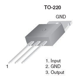
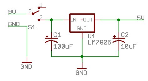
Here you can see the 'pin-out' of the LM7805. Say 'IGO' in your head and commit this to memory (input, ground, output). You'll probably hook up a lot of these. When in doubt, always check the datasheet before hooking up a new part - or else be close to the on/off switch! Input is the input voltage of anything greater than about 7V. GND is ground. Output is the 5V output pin. Your wall wart should have two wires. One is 9V, the other is GND. All grounds need to be connected together for current to flow across the system. One more time - connect all grounds. This is the #2 reason why novii can't get a system to work. For our breadboard, we will be inputting 9V (or whatever transformer you've got up to about 15V) and outputting 0V (GND) and 5V to our breadboard rails.
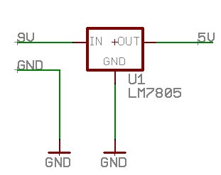
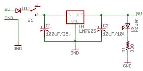
We are going to go through a bunch of iterations of the power supply, adding parts as we go. Shown above, we have a basic regulator configuration. 9V in, we should see a rough 5V on the output.
Schematic note: The two ground pins are not shown connected. We assume that nets (the green wires) of the same name are connected together. Schematics can get big and complex, so you won't see all the wires together, but in your breadboard you need to connect all the GND pins together. In this case it's the GND wire from your wall wart connected to the GND pin on the regulator.
Cool. But why doesn't the multimeter read 5.000V? Electronics are not that good. The cheap-o regulators are +/-5% tolerant meaning you'll see between 5.25 and 4.75V. In practice, you should see between 5.1 and 4.9V with most run of the mill regulators. You can of course spend many $$ and get tighter tolerances but 5.1-4.9V will work fine for our purposes.
Now we should be worried about ripple. There is noise coming in the input pin, the regulator tries hard, but some of that noise gets onto the output pin. Your multimeter says 5.08V, but that's because it's averaging many readings together and showing you only the average. Do you know someone with a oscilloscope? If so, show them this tutorial and ask them to show you the noise on your 5V rail. With no filtering caps, you could see as much as 200mV of noise.
Whoa - what's a filtering cap? Filtering capacitors are large bulky capacitors that help smooth out ripple. There've been lots of analogies about capacitors so here's another one for ya:
Capacitors act like water tanks. When your circuit pulls a bunch of water out of the system, the capacitor helps hold the voltage up temporarily until the power system can catch up. For example: you may live in a city with water and water pressure. If you take a shower you affect the pressure in the municipal water system ever so slightly. If everyone turned on their shower and flushed every toilet in the city, odds are the water pressure would fluctuate quite a bit! A big water tank helps minimize these pressure fluctuations. A big cap helps minimize the voltage fluctuations on your breadboard.
Is this something you can see happen? Unfortunately not really. You can probably run your system without filtering caps, but it's not good engineering practice. Give it a whirl without caps! But when things don't work, you'll wonder if it's the caps, or your code, or your timing, or maybe you blew out the sensor. Too many unknowns will make you crazy. My recommendation: just use a couple basic caps...
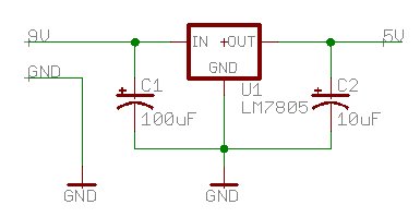
100uF (one-hundred micro farad) on the input and 10uF on the output. You will use a lot of 100uF and 10uF around power systems and you will eat 0.1uF (point one micro farad) caps like candy around micros. These two caps should smooth the input into the regulator and will smooth the output nicely.
Capacitors cannot deliver their stored energy instantaneously. Larger caps (1ouF and 100uF) store more energy, but they react more slowly. The smaller the capacitor, the faster it can deliver its stored energy. If you have a large power outage (power dips for 10-100ms), a big cap (100uF to 1000uF) will help 'hold up' the falling voltage. A smaller cap (0.1uF) will help suppress higher frequency noise and shorter power dips (noise in the 1us to 100us range). Therefore, 0.1uF caps are located near the microcontroller to help with short bursts, where 100uF and 10uF caps are used on the power rails.
Now you see the schematic symbol looks a bit odd. What's with + and curved lines? This schematic component is indicating that the 100uF and 10uF cap are polarized. Oh jeebus, what's that? Time for a capacitor breakdown:
-
Electrolytic caps: These are larger caps capable of storing 10uF to 1,000,000s of farads. They are cheap and great for bulk capacitance. They are polarized meaning there is a positive pin and a negative pin.
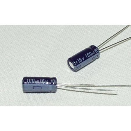
The cap has a minus '-' sign on the cover indicating that pin needs to go to GND.
-
Ceramic caps: These are the cheapest and most common cap you'll play with on a breadboard. They are NOT polarized so you can stick em in the breadboard any way you want. Ceramic caps cannot handle as large of capacitance as electrolytics so you'll need both on your breadboard system.
-
There are many more different kinds of capacitors but for the sake of your head exploding, we won't cover them here.
Okay - now you need to work through some logic here. You know the positive part of the 100uF cap needs to be connected to the input pin, but only the negative pin is marked. Yes it's confusing - but you'll get used to it. Negative marked pin goes to ground, the other goes to the input pin.
What happens if you get them switched? Well here's where things may go poof.
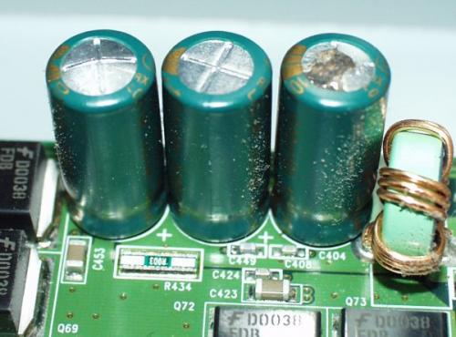
From the left: Bad, good, ugly
This is what happens when you over-voltage or reverse voltage a polarized capacitor. The middle cap is normal. The cap on the left, you can see the top is slightly raised up. This is what happens when the electrolyte inside expands. And the cap on the right shows us what happens when this pressure is so great, it busts through the metal top. Notice the '+' imprinted into the tops of these caps? That imprint is there so that if the pressure does build up, the cap will fail like the unit on the right - rather than blowing the top half of the cap across the room.
This picture was taken from the inside of an old Gateway computer (circa 1999). Gateway had used some 'marginal' 1000uF/16V capacitors. The /16V means they are rated to 16V. A 16V rating means they can withstand voltages up to 16V but no more. These caps were sitting on the 12V rail to smooth out the ripple but obviously they where failing. Gateway was trying to save $0.50 by using a capacitor that was too close to the maximum. Manufacturing is not perfect! With any production run, the population of capacitors and their tolerance looks like a bell curve. The majority of the 16V rated caps can withstand 16V. Some can 18V, even 22V! But the tolerance bell curve goes both ways; a small number of the capacitors rated at 16V will fail at 10V, some at 8V. You get a big enough ripple on the 12V line and you could pop the 16V rated cap. This is why most engineers talk of 'de-rating' capacitors. If you have a 5V rail, you do not stick a 5V rated cap on the rail! A good rule of thumb is to de-rate any capacitor by 50%. So a 12V cap is good to be used on 6V rail, 24V cap on a 12V rail, etc.
Guess what happens when an electrolytic cap fails like the ones above? They quit working. In most cases, they 'fail safe' meaning they won't work as a capacitor anymore but they won't short to ground. The real fun begins when the failure is so bad that the internals fuse together and you get a short to ground - then you can have some fun melt downs! In the case of this computer, the motherboard had all sorts of bad software failures because the power supply had too much ripple! The big filtering caps on the power supply had failed so the 12V was all over the place.
Similar failures can happen if you reverse the polarization of the cap. If the voltage is low (less than around 25V) the cap will probably just be damaged a bit. If you've got a vacuum bell sitting around and you want to really cause some damage, ask a trained professional to hook up 10V cap backwards to 10,000V. It should instantaneously blow up like a pop corn kernel.
For your power supply filtering caps, I recommend using a 25V rated 100uF cap (100uF/25V) on the input and a 10uF/10V cap on the output. Engineers will tell you to 'derate' the cap by 50% meaning if the label says 100V don't trust it past 50V. This is generally good practice. Following this idea, our 100uF/25V is good for inputs up to about 12.5V before we should worry that we may pop the electrolytes. Again, not mandatory, just don't expect a 5V rated cap to withstand a 9V input.
Back to our power supply! Don't worry about blowing things up just yet, you should be at low enough voltages you won't do any harm. Again, if things heat up/smoke/spark, just unplug or turn off the system. Speaking of turning things off - we need a power switch!
This will allow you to turn on/off the system. Handy. It can get really annoying pulling and inserting the power wires to power/kill your system.
Inside the small black enclosure, is a switch. The switch has three pins. It looks like a see-saw inside. The center pin is always connected to the middle of the see-saw and as you slide the switch back and forth, the see-saw rocks up and down. Slide the switch forward and the see-saw shorts from the center pin to the forward pin. Slide the switch back and the see-saw disconnects from the forward pin and shorts to the rear pin. We recommend you connect power to the center pin of the switch. When you slide the switch forward, power will short to an unconnected pin and do nothing (no power to your system). Slide the switch back and the center power pin will short to the wire running into your regulator, delivering power to your system (power on!).
Remember all the warning about reversing VCC and GND and how that is bad? Well if you connect your power supply backwards, that's bad. So let's protect ourselves!
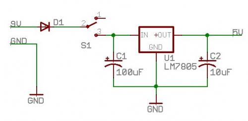
That's a diode (marked D1). A diode lets current flow in one direction (in the direction of the arrow) and it blocks current from flowing in the opposite direction. This will allow 9V to flow in the right direction, and if you accidentally hook your power supply up the wrong way, it will block current from flowing backwards and damaging your system. Is it overkill? Pretty close. But we always design them into our development boards because we don't know what type of power supply you knuckleheads (also known as our paying customers) will plug on to our boards. If you plug the wrong type of wall wart onto a board, we want to protect you from yourself.
There are some down sides to a protection diode:
-
All diodes have a voltage drop, meaning 9V on one side will drop to about 8.5V on the other. So your 9V wall wart just became 8.5V.
-
Diodes have a current rating. If you try to suck 1A (1 amp) through a 0.1A (one hundred mili-amp) rated diode, the diode will quickly heat up and fail. For reverse protection, we recommend a 1A 1N4001 diode. These are dirt cheap and very common.
Note that diodes are polarized. They have a direction that you need to pay attention to. Many diodes have a band indicating the cathode. What's a cathode? Go google. All you really need to know is that the line on the schematic part is the same as the line on the diode. If you can't remember which is which, remember 'arrow is for anode'. Cheesy, yes.
So if you want to install this 'reverse protection diode', the 9V from your wall wart goes into the end of the diode without the band (the anode). The banded end (cathode) goes into your switch. Your switch then goes into the input. Throw the switch and you should see 5V on the output using your multimeter. Nifty. But I am tired of using my multimeter each time to check the 5V output. There must be a better way! Time to wire in the power LED.
Light emitting diodes (LEDs) are bits of silicon that light up when current flows through them. Go google for the science. As a general rule of thumb, LEDs can have 20mA max current flowing through them before they begin to fail.
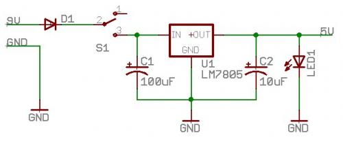
So if you hooked up your LED like in the above schematic, it would light up very bright for a split second and then burn out. That's cause the LED is a diode and the current will flow from the anode (arrow) to the cathode (line) to ground - uncontrolled! The silicon will flow current at something like 1 amp for a split second and burn up. To limit this current flow to 20mA, we need Ohm's law. Yea, the book worms in the room suddenly perked up:
V = IR (this is Ohm's law)
If we have 5V, and we only want 20mA flowing through the LED:
5V = 0.02 * R
R = 250 Ohm
Now this is not completely true because the LED has a forward voltage drop, but don't worry too much about that. Hooking up LEDs is very common with micros. All you need to remember is that you're going to need to limit the current. The most basic way to do this is with a resistor. 220 Ohms will work (LED will be brighter), 330Ohm is also good (LED a bit dimmer), 1K (1000) will work as well. 220, 330, and 1K are more common resistor values.
I highly recommend you get your hands dirty. Hook up an LED to a 1k resistor, then a 330, then a 220, 100, 50, then finally blow the thing up by hooking it with no resistor. That was fun right? Good. You had a back-up right? Once the bit of silicon inside the LED is burned out, it is no good and the LED can be thrown away.
Our final power supply circuit. It seems like a lot of work, but once you set this up on your breadboard, you might never take it off. This is the basis for all things micro. The input voltage may change, the output voltage may change (to 3.3V for example), but the basics are all there. Flip the switch and you should have a nice 5V rail and an LED letting you know that everything is a-ok. If the LED does not light up, that means that something else on the 5V rail is sucking so much current that the LED cannot light up. This is a very strong indicator something is wrong. If you turn on your system and the Power LED does not turn on, immediately turn off the system and check your wiring.
You may be wondering if the resistor/LED order matters. It does not. The resistor can come first and then the LED or as shown. Either configuration will correctly limit current through the LED.
If you think you may have blown up your LED then your LED will never turn on. You may want to check your power system with a multimeter instead.
Good, you've made it this far. Now for some technical info about ripple/noise and why it's bad.
If you've got major ripple on your power rail, say 500mV or more, this can cause your micro to latchup. This means that it was running fine at 4.8V, but at 4.3V it's not happy and will go into an unknown state. When the rail returns to 4.8V (because the ripple is bouncing the rail up and down), the micro goes from unknown to possibly latching up or freezing up. This is pretty rare these days because the chip manufacturers have done a good job of internally protecting against this, but in general, ripple is bad.
Say you've got 500mV of ripple on your system and you're doing analog to digital conversions off of a temperature sensor. The temp sensor has an output pin that will output an analog voltage that will vary 100mV for every 1 degree C. So at 25 degrees C (room temperature) the sensor will output 2500mV or 2.5V. If your micro is doing analog-to-digital conversions on this signal, it has to compare what it 'thinks' is a solid power rail of 5V against this changing analog signal from the temperature sensor. Well if your 5V 'solid' rail has 500mV of ripple, the micro doesn't know this, and will report a regular 2.5V reading as varying between ~3.0V (3000mV = 30C) and ~2.0V (2000mV = 20C). This is wildly bad. You need a good 'clean' power rail if you are doing anything with analog signals.
Now some notes and photos on breadboards:
Go read Tom Igoe's breakdown of the breadboard. In short, the power rails (the red/blue rows) are connected internally. The columns within the main area of the board are interconnected. So you can insert a wire into one hole and it will be electrically connected to a neighboring hole (vertical connections for the numbered columns, and horizontal connections for the blue/red power rails).
Historically, the blue rail or the horizontal row of holes next to the blue line is 'GND' or ground. You can connect all the ground pins of all your components to this rail. Similarly, the red rail is for VCC. In our case, this is 5 volts.
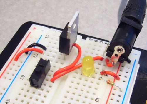
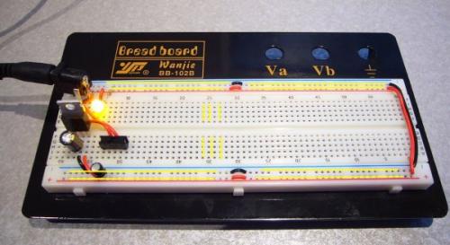
Power jack, switch, LM7805, power LED
Here you can see power from the barrel jack being delivered to the slide switch, and then to the input pin of the v-reg. When the switch is thrown to the on position, the yellow LED turns on.
I cheated a bit.
Do you see that odd thing in the upper right corner of the picture? That is my wall wart plugged into a DC barrel jack. Most wall warts are terminated with a round connector called a 'barrel'. The outside metal sheath is ground, and the inside metal is 9V. The two metal contacts are isolated. The DC barrel jack accepts this wall wart barrel (wall wart barrel slides into the jack with some friction to hold it in place). I don't like hacking the ends off power supplies and inserting the bare wires into a breadboard. Having energized bare wires bothers me. If the wires get pulled out of the breadboard because you kicked out the power cord, you'll have some tense moments until you get the power brick unplugged. So I soldered some short leads to the barrel jack so that I can plug/unplug my power cable from the breadboard. Easier to transport.
See the orange wire at the end of the barrel jack? That pin inside the DC barrel jack connects to the center of the wall wart barrel. The center of our wall wart barrel connectors are '+' or 'hot' or '9V', whatever you want to call it. So the end of the DC barrel jack is soldered to an orange wiring meaning it is '+'. This orange wire is then connected to the center pin of the power switch.
All ground connections are connected together. You will see a small black wire underneath the DC barrel jack. This is the pin that connects to the outside sheath of the wall wart barrel. This is the ground connection on the wall wart. This small black wire connects the ground of the wall wart to the ground on the breadboard.
I did not install a reverse protection diode. I *only* use center positive power supplies so I know I'm safe. If you do anything similar, check your wall wart carefully with a multimeter before doing any testing.
Note: Our breadboard will have 5V and 0V rails. The blue rail is GND (considered 0V). Red is VCC (or called 5V).
Note on LEDs: LEDs are a polar device meaning you've got to hook them up in the correct direction. Light emitting diodes (LED) have a cathode and an anode. How do you tell the difference? Imagine the schematic element:

An LED
Do you see the arrow? Do you see the flat line? A is for arrow. A is for anode. The physical LED will have a flat side corresponding to the flat line (the cathode) in the schematic picture. And there you go! When connecting an LED, you know that diodes only pass current in one direction (from anode to cathode - in the direction of the arrow!) so the flat side of the LED needs to be connected to ground some how (usually through a resistor first) and the other side (remember arrow) is the anode and needs to be connected to power for current to flow. If you hook it up backwards, it won't turn on, and you might damage the LED but probably not. Just verify that you've got 5V on the correct rail and then flip your LED around if need be.
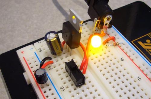
Note the polarization of the caps. The larger 100uF cap is directly connected to the Input and GND pins of the v-reg. The '-' sign is connected to the ground pin. The smaller 10uF is connected on the power rails. The '-' sign (in white) is connected to ground, the opposite leg is inserted into the '+' rail. The power LED is on!
Note: The center pin of the wall transformer is connected to the red wire on the rear of the barrel jack. This short wire is then routed by another wire to the slide switch. Do not connect this center pin/9V source to the power rail on your breadboard!
The slide switch has three legs. The center pin is considered the 'common' pin. If the switch is thrown to the right, there is a connection from the center pin to the right pin. Slide it to the left and a connection to the left pin is made. When dealing with power, we want the raw voltage (9V in our case) delivered to the center pin of the switch. When I slide the switch to the left (as pictured above), current is allowed to flow from the center pin to the left pin and on to the voltage regulator. When I slide the switch to the right, the center pin is connected to the right pin (which is not connected to anything). In this state, current does not flow anywhere and the breadboard remains powered down. Voila! We have a power switch.
This picture is key. When I initially wired up this circuit, I flipped the switch and the power LED didn't light. That was VERY bad indicating there is a massive short somewhere. Even the good guys screw up now and again. Whip out your trusty multimeter and start probing in continuity mode.
Quick note: I highly recommend you purchase a multimeter with a 'continuity' feature built in. This mode allows you to 'tone' out circuits. In this mode, if you touch the two probes together, you should hear a tone indicating that there is a direct connection between one probe and the other (obviously - you have them touching!). This feature is used countless times during trouble shooting. In the above example, by probing from one GND rail to another, I noticed that I could not get a tone. Therefore, there was a break in the circuit somewhere which lead me to realize the break is in the rails.
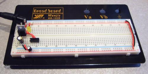
If you've got a medium sized breadboard such as the one shown above, you'll notice something horribly odd. The various holes of the power rails are not connected!
There is a reason why the power rails are broken. If you have a breadboard with multiple and different power rails, you cannot share them on the same row of holes. So modern breadboards break the rails up so that you can isolate different parts of your circuit. For example, if you were building a really complex design you may need to have 5V and 3.3V on the same board. Because the rails are isolated from each other, you could just use various strips around your breadboard to be designed at 5V, 2.8V, etc. For the purposes of this tutorial (and for almost all breadboarding) we assume that you'll only be using 5V and GND. Therefore, we need to use short jumper wires to interconnect all the isolated rails, forming one continuous 5V rail and one continuous GND rail.
When I first wired up my power supply, I only had the long black/red jumpers on the right side of the board, but didn't have the small jumpers in the middle of the rails. Without these middle jumpers, only the bottom left rails (next to the 5V supply) actually have 5V and GND. Since the LED is connected to the upper left power and ground rails, the LED never got power! Therefore, you will probably need to use very short jumper wires (and some long ones on the end) to connect all the '+' rails (5V) together and all the '-' rails (GND) together.
Some additional nit-picky notes about breadboarding:
- You won't listen to this rule. Neither did I initially. Use a few different colors of wire! It's really helpful to see where the power and gnd wires go if GND is black and 5V is red. I wired 200 connections using only orange. When things didn't work, it was hard to figure out where all the connections went.
- Don't worry about super-tight wires, and don't use huge loops. When cutting and stripping wire for breadboard connections, don't spend exorbitant amounts of time making the wire perfectly flat. It doesn't matter. That said, don't use 9" of wire when 1" will do. Make it clean.
- The 'making things clean' rule applies to LEDs, resistors, and crystals as well. Clip the legs! If you've got OCD like I do, it can be hard to permanently alter a part in this way. What if I need the legs to reach further away on a future project?! It's ok. Resistors cost $0.005 each. If in the future, you need a resistor with full legs to reach from point A to point B, just get a new one. It's not worth having lots of exposed legs that could bend and short to other exposed legs.
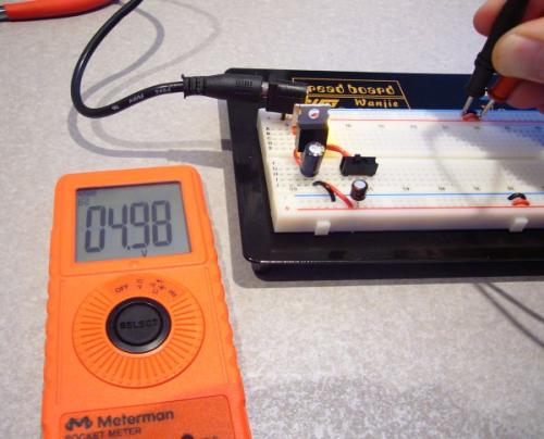
Now with your power supply built up, turn your multimeter to voltage and check your board voltage by probing from the Blue rail (0V or GND) and the red rail (5V or VCC).
Note: To use a multimeter you need to use both probes. Voltage refers to a potential. Using only one probe will get you nothing because you have to compare something against something else. In our world, we assume ground is 0V. So touch your black probe to any ground connection. Now you can measure the voltage on any other pin with the red probe. In the picture below, the black probe is touching the ground rail (0V), and the red probe is touching the 5V rail - thus we are viewing what voltage is exposed on the red probe compared to ground. If we put both probes on the 5V rail, the multimeter would show 0V because there is no difference in voltage between the probes.
Guess what happens when you push the black probe against the 5V rail and the red probe against the ground rail? The multimeter will show -5V. This is because the multimeter assumes the black probe is touching 0V. There is still a difference of 5V between the probes so the multimeter shows -5V.
So you don't have 5.000V. Nothing in engineering is perfect. If you're within 100mV you're doing just fine. These cheap-o voltage regulators are cheap for a reason - and we don't need high-precision. 4.9V to 5.1V is just fine.
Congratulations! You've built up your very first breadboard! Now leave this 5V power supply wired in your breadboard! You are going to use it many times...
Quick Note: PTCs are your friend! PTC = positive temperature coefficient. Beginners will often create shorts or accidentally hook things up backwards. A PTC (also known as a thermistor) is a device that will increase in resistance as current flows through it. These PTCs can be designed so that at a certain current flow (let's say 500mA), the resistance increases dramatically, thus limiting the current flow. Basically, the PTC acts as a resettable fuse! You will want to place this device in series, before your voltage regulator. If your circuit draws more than 500mA (if you short power to ground for instance), the PTC will heat up and limit the current to 250mA. Once you remove the short, the current will drop back down, the PTC will cool off and the circuit will start operating normally again. Very cool little component that has saved many of my designs from smoking.

This is how the PTC looks in circuit. The PTC is wired in line. As the current of the circuit flows through the PTC, it will trip if the current is too large, cutting off the rest of the system.
Beginning Embedded Electronics Tutorial Pages
- Lecture 1 - Background and Power Supply
- Lecture 2 - How to Get Code Onto a Microcontroller
- Lecture 3 - What is an oscillator?
- Lecture 4 - UART and Serial Communication
- Lecture 5 - AVR GCC Compiling
- Lecture 6 - Soldering Basics
- Lecture 7 - SMD Soldering
- Lecture 8 - Eagle: Schematics
- Lecture 9 - Eagle: PCB Layout
- Lecture 10 - Eagle: Creating a new part
- Common Mistakes, Tips and Tricks
We love feedback! Please report typos, comments, or recommendations to spark@sparkfun.com.
Very good write-up, I do have a question though regarding the use of capacitors for the power supply. You are recommending 100 uF on the input line and 10 mF on the output line. Spec sheet for the LM7805 recommends 0.33 uF on the input line and 0.1 uF on the output line, substantially different values. Why?
Also, the spec sheet for the voltage regulator that I actually have at hand LM2940CT-5.0 recommends 0.47 uF on the input line and 22 uF or larger on the output line. I am not concerned with the exact value here but they recommend larger cap on the output line contrary to what you are explaining. Any suggestion why?
if you just need to get some pretty lights blinking (for an art project or something), and you find these tutorials overwhelming (even though they're awesome (!!)), you may want to start with an arduino programmer instead:
Arduino USB Board
http://www.sparkfun.com/commerce/product_info.php?products_id=666
http://www.arduino.cc/
it is still recommended that you read through the tutorials (^_^)/
really nice tutorial, i actually read the whole thing, and i never knew i could get so excited about a regulated power supply.. :D
Thanks a lot, this tutorial is great, it has everything an electronic should know, even the obvious but tricky things. I saved it completely.
Yes, I noticed this earlier today and let stilldavid know. However, as I have noticed after a couple beers (yes it must help me think) that just the directory has moved, so for each image, just change
http://www.sparkfun.com/images/tutorials/BEE-Lectures/*
to
http://www.sparkfun.com/tutorial/BeginningEmbedded/*
example:-> Change
http://www.sparkfun.com/images/tutorials/BEE-Lectures/1-PowerSupply/BB-PowerSupply-4.jpg
to
http://www.sparkfun.com/tutorial/BeginningEmbedded/1-PowerSupply/BB-PowerSupply-4.jpg
and you will get your pictures.
You have a spelling error in your OR microcontroller code.
if (A == 1 || B == 1)
{
C = 1;
}
else
{
C = 0;
{
If you would notice the very last bracket is an opening bracket not a closing bracket.
Very nice tutorial!
best tutorial so far. two downsides though:
- gray isn't the best color for this kind of reading.
- a printable version should be made availabe, if it hasn't been already.
never the less, good job :)
Well, this kind of 5V source isn't the type I'd use. It wastes almost 50% of the power. This means that your 9V battery will last almost the half it should with a well made 5v source. There are some IC's from maxim that achieve high efficiencies. I've learned that in battery powered projects one should be as efficient as possible. Anyway, I think it's a well made tutorial and it's a good starting source for one's first projects. By the way, you are so right about the PTCs. I've seen several of my most sensitive IC's smoke to death in an instant and not because of short circuits. When using batteries one has to take into account the short circuit current it gives. It may be too small (CR2032 for example) or too high and may give trouble because there's no limit. PTCs are life savers.
Great tutorials! I really like to print out tutorials and follow along, esp. when they are long like this. Is there a better way to print these tutorials? The light gray text and gray columns on the side make it a real pain to print and read. Is there a PDF or print-formatted version available?
Thanks and keep up the great tutorials!
Thanks for a great tutorial. I've been wondering about these little switches used in breadboard power circuits -- they're all pretty wimpy in the current department, e.g., the one listed in the parts kit for this tutorial is rated at 200mA. Doesn't that mean that the entire current usage of the design hooked up to the supply circuit is limited to 200mA before the switch will weld open or otherwise destruct?
All the beefier switches (1A+) that I've seen are huge and don't have pins suitable for direct/convenient use on a breadboard. Are there higher rated but BB-friendly (no soldering required) switches available? (Where?)
thanks!
I'd suggest semiconductor switching using a transistor rated for adequate current. Use the wimpy switch to "turn on" the base or gate of your transistor, and the transistor handles all current.
Thanks for very very helpful, easy to understand tutorial.
But, i have a question. How should we use PTC?
Serial connection as a resistor or like a cap?
It would be very good if you can integrate PTC to schematic.
Good question - it is wired in line. I've added an updated schematic upon your request. Checkout the end of this page near the PTC image.
Thanks for writing that article, I've learned more from reading this than I have in a long time! Very well written and easy to understand, which is different from many other books and articles I've tried to read on electronics.
That was really nice tutorial. I have a bachelors in engineering and have not used electronic circuits in a while, so it really helped refresh a lot of things. Thanks for doing that.
Are there other tutorials in this series - Beginning Embedded Electronics? Thanks!
There is a whole category here. Be sure to checkout our more recent concept tutorials as well.
I understand why a resistor is needed at D2, but why isn't needed at D1?
Nice intro to microcontrollers. But the tutorial is broken. I cannot see anything beyond the "Note on LEDs". This is an awesome write-up. Please fix ASAP.
We'll try to get this one fixed up. For now, I'd recommend checking out our new, up-to-date tutorials on beginning electronics here.
This is a great tutorial! Thank your for posting it. And i have a question about the ADC with ripple on the system. If the 5V rail has 500mV of ripple (10% of the reference voltage), I think the micro will report a regular 2.5V reading as varing between 2.5V/110% and 2.5V/90%, i.e. ~2.27V and ~2.78V. Am i right?
would this circuit power an xbee ok with a 3.3V voltage regulator instead?
I know this is a several-year-old article, but I really hope you're still responding to questions on it: Would this circuit be appropriate for taking an automotive 12VDC power source and stepping it down to 5VDC for an ATMEGA328? I know automotive power is very noisy, but the project I'm about to begin will be dashboard-mounted and will use one of the car stereo power source wires for juice.
Thanks to a neat feature on our website, we can see when people post comments to anything we've authored. I may not be able to respond to everything, but happy to help out where possible:
This power supply configuration should work well in an automotive application. The filtering caps and linear regulator should remove most of the noise around the 12V rail. On the 12V input to the regulator be sure to use caps that are properly voltage rated (25V or higher). Note: the linear regulator will have to dissipate a lot of heat to get 12V down to 5V. If you're pulling <100mA you should be okay without a heat sink but consider adding one just in case.
This is a great tutorial! One question though -- I bought the power supply kit (KIT-08373) that has all the parts used in this tutorial, but there's a part left over, the resettable fuse (a 500ma PTC). Just for kicks, I put this in line with the diode, before the switch, and everything works fine. I haven't tried this yet, but I assume that if i just short from 5v to ground, that will trip the fuse, so that none of the other parts get blown. Is this a correct assumption? I suppose I could just try it and see what smokes, but I'll wait a bit to see if anyone responds ;)
Typo if you are correcting them: Page 5 (lecture 1)::: The cheap-o regulators are +/-5% tolerant [TOLERANCE]. Excellent tutorial
Thanks for the feedback! Fixed.
Nate - you are awesome. Thanks for writing this.
Hi.Thanks very much for your tutorial.
Any chance I could use a 9V battery instead of a 9V wall charger in your tutorial?
Excellent tutorial. I have never picked up a breadboard or put even the most basic of circuits together. Following your instructions I was able to do it right the first time. I've plugged in all kinds of leds including some RGB ones..too much blowing them up ; )
Going back and rereading this, I didn't quite understand this line.... "You may be wondering if the resistor/LED order matters. It does not. The resistor can come first and then the LED or as shown. Either configuration will correctly limit current through the LED"
The resistor can come first how?
This tutorial is really great and really wet my whistle for electronics. As I continued to read other beginning electronics books (while I wait for my Begining Embedded Electronics Kit to arrive, I found other information that confused me regarding Ohm's Law because you didn't include it herein (so I doubted the new information was correct since this tutorial is so good!). However (as I'm sure anyone but a complete noob like me is aware) you can subtract the voltage drop (forward voltage) of the LED in the Ohm's Law equation, in order to determine the ideal brightness of the LED. Per the LED Datasheet the forward drop of the LED is 2.0-2.4v at 20mA. Using the lowest voltage the correct formula would be R = (Vin - Vforward) / I or R = (5v - 2.0v) / 20mA = 3v / 2ma = 150 ohms. Don't forget if you are going to use a resistor with +/- 20% accuracy then you should use a 190 ohm resistor to be safe.
Hi, really great tutorial, just one question: if I want to power an arduino micro that must be powered over 7 volts but i want to use the regulated 5 volts line for powering loads bypassing arduino 5v output i just connect arduino VI after the 100 uF capacitor but before the voltage divider is it right? Do you think this will lead to problems due to the different noise on my arduino and the main power source line? I need to read low analog values from 5 IR proximity sensor. Tx Gabriele
Hello!!
Really nice guidance given by you. I made this circuit 3 days before and it was working fine and was showing 5.2V. Suddenly from today it has started responding erratically. Today when i measured the voltage it is showing 10V. Kindly help me out.
Wow! Great tutorial! I just raised my cart price $100 ;) No, I'm not kidding!
Umm, isn't the first bit of code mostly equivalent to C = A || B; ? I'm not sure this kind of verbosity makes a great example of coding.
Is this level of voltage regulation necessary for a DC-based power supply (e.g., batteries), or can I omit the 2 capacitors and just go with the voltage regular and diode for a battery-based power source?
Thank you thank you thank you
THANK YOU THANK YOU!!!
Great tutorial!
I am not able to see any pictures on this tutorial. Looks like the links are broken. Sparkfun: Can you please fix the pictures
They should be working for you now. If you are still running into issues, please let us know.
I wish your section on microcontrollers wasn't so biased against PICs. I'm not saying that anyone should switch to them -- the lack of an open source compiler is what really kills them -- but PICs are often cheaper than AVRs, have more peripherals, and are more stable. 8-bit PICs have had USB for a long time now, Atmega has only just gotten around to that. It should also be noted that you can't accidentally brick a PIC if the voltage drops while programming.
ARMs that are comparable to PICs, AVRs and MSPs are low cost, but ARMs in general are higher processing power controllers, and cost more to make up for it.
The "major misconception" link is now broken.
"highly recommend you get your hands dirty. Hook up an LED to a 1k resistor, then a 330, then a 220, 100, 50, then finally blow the thing up by hooking it with no resistor."
Using this method, but using an arduino Uno board that outputs 5v dc I wasn't able to blow the LED. Is this due to the voltage drop across the LED?
Something to consider... The protection diode in this circuit offers only half-wave rectification which is a very inefficient use of power. A buck more on the circuit by adding a bridge rectifier ensures that no matter how your wall wort is connected, VCC will flow to ground on the expected pins.
The pros of a full wave bridge rectifier are huge in cases where you don't know what kind of power supply you or your customers may use. Furthermore bridge rectifiers are typically marked with (+,~,-,~) so you have built in documentation of the current's flow on the board.
A nice little write up, amongst many is offered here
Would be a nice product to offer as well ;)
The only problem with using a full wave bridge rectifier is that Voltage drop across two diodes, instead of Nate's one diode drop. I don't remember what Nate was giving for the value for the voltage drop, but if my memory serves correctly each diode normally it's around .75 per diode.
As Nate said >>
There are some down sides to a protection diode:
All diodes have a voltage drop, meaning 9V on one side will drop to about 8.5V on the other. So your 9V wall wart just became 8.5V.
Well if you use the .75 voltage drop times 2 diodes, you get a 1.5 voltage drop; that means your 9 volt wall wart became 7.5Volts power supply. If your project does not mind a lower voltage before the regulator, go for it. But if you got some power hogs that switch on and off or you have some fast CMOS running above 40mhz(-that could be 20Mhz) you’re going to need to add some .01-.1µF and 10µF s to compensate for those ripples on your power rails.
In the old days of TTL (Transistor to Transistor Logic), you were suggested to add a .1µF across each IC, and it was suggested to add a 10µF where the power entered or left a PCB. Then again in the old days of TTL it was not uncommon to see 12VDC supply feeding a bunch of 5V regulators which fed all the TTL gates. TTL just love to eat power. That also was when it was not uncommon to find a Fairchild 5 volt regulator running at 3 to 10 amps (you could arc weld with the 12V supply side) . That's when 74LSxx became popular, followed by the 74ALSxx (Advanced Low Power Schottky), and finely over to the 74HCxx (High speed CMOS) and the 74HCTxx(High speed, compatible logic levels to bipolar parts)- but that's another subject...
Maybe Nate will get around to talking about using switching power supplies, which for one run cooler and use less power- less power goes up in heat to give you that smaller voltage. Then again you’re going have to add caps across the rails to compensate for the high frequency spikes that can show up on your power rails.
I ordered the kit and I'm having a problem. If you face the breadboard forward, with "Bread Board Model: ZY-20i" at the top, the side of the board reads, going down, "j i h g f e d c b a" but on the pictures it shows "a b c d e f g h i j" going down. Do I put everything in basing it on the "Bread Board" sign, or do I follow the letters?
I'm not able to load any of the pictures in this tutorial and some of the pictures in the following ones. I'm not sure if it's maybe because I changed some of my browser settings. I think I was able to see the pics earlier this month.
It isn't just you. I believe they are currently working on getting the images back.
Thanks, Paradoxial, for the reply. It was helpful to know that I wasn't the only one who couldn't see the pics. Sorry about my really late thanks reply.
And thanks, SparkFun, for fixing the pics, and for creating/maintaining these tutorials. They are awesome!
Safety Note!
That's not what an electrolytic cap looks like if you reverse voltage it. If you want to try and see what it really looks like, do it outside, wear safety goggles, and stay at least 10 feet away! They pretty much go like firecrackers - but don't really.
Seriously, DON'T reverse connect them even for fun -- you may get injured. Be carefull to always put them in right.
BTW, about 90% of failed electronics in my experience (monitors, motherboards, power supplies, radios, cfl bulbs etc) go bad from bad caps (leaking electrolyte). Not too bad to replace and a lot of times you can save the item. I've saved 3 out of 5 bad lcd monitors, and 5 out of 10 motherboards by replacing the bulging caps. The success rate is better if you can replace them before the device starts failing (when they fail, they often short and take other parts out with them). I'd recommend too, when buying motherboards, look for ones with Japanese and/or solid electrolyte electrolytic capacitors.
Cheero!
Mark.
Great tutorials! congratulations!
Just would like to say, Half of the images in this tutorial are still broken, but it isn't just this tutorial, I saw it happen to a bunch of tutorials.
some of this is good, but a lot of Beginning Embedded Electronics needs to be updated
Why don't the pictures work for this tutorial?
I am having the same problem.Also,there is some "Permission Denied" error, when I try to view the images separately.
Me too. Sup with that?
on all tutorials i cant wiew images. i sended a email to sparkfun.
Yup, thanks for the heads up, all! Fixed now.
Hi,
Seems like the pictures went missing again :(
Woa!! I sent an email to Linz about the broken images and then a few minutes later it was fixed...Looks like you were fixing it right then.
Looks good. thanks
Hi!
Great Tutorial, thanks a lot! I just have a quick question. Why do you put the caps parallel? How does that work? I always thought if you put something parallel you have the same voltage, but obviously there is 9V on one cap and 5V on the other. How does that work?
Please explain
Never mind, found the answer myself...the 10 uF cap is in series with the regulator, and them two are parallel to the other cap. Thanks anyway!
Not quite true. Both caps are installed parallel to the vreg. They have to be, as they block DC current once they are fully charged. If your oscilloscope shows output power of 5v for a few seconds, then drops to 0v, you may have installed a capacitor in series.
Thanks I know absolutely nothing about electronics and was able to build the bread board in just three evenings.I even used and lit up the extra LED "Wow"<br />
<br />
The thing I don't really understand about bread boards is how the hole/rows are configured. If you are in row 5, for instance is the row 6 always meant to be the ground row? Or is each row isolated from the other?<br />
<br />
Also I start with AC current in the house but the when you go into the bread board now there is a ground. Is this still AC current now or does it turn into DC. Thanks in advance I love this site.
Excellent tutorial! I had never thought about using a PTC in a voltage supply before, its perfect so a beginner like me won't burn up any components.
I don't totally understand this part:
In the old days, microcontrollers were OTP or one-time-programmable meaning you could only program the micro once, test the code, and if your code didn't work, you threw it out and tried again. Now micros are 'flash' based meaning they have flash memory built inside that allows their code to be written and rewritten thousands of times. I've been programming micros for years and always burn out the microcontroller far before I hit the limit of flash programming cycles.
I get that it means you can program them more than once now, but I am unsure as to what is meant by programming
This is a great lecture and it gets all this cool raw electronics gear in your hands. Pretty new to electronics so this is perfect. This simple circuit put together with an LED and everything, taken along with the first 50 pages or so of Electrical Engineering 101, has really helped me to feel like I got my feet wet. Fun!
http://www.sparkfun.com/commerce/product_info.php?products_id=9458
I hope you know that the technical name for an LED that has had too much forward or reverse current through it is a DED: Dark Emitting Diode.
Please modify your tutorial accordingly. :-)
Thanks for the information, and input. We will make some changes.
Agree that the AVR stuff is fun to play with at the price point, but have recently been doing MSP430 stuff at work and ran across a deal that might be interesting for some readers. $4.30 for a couple of "value line" MSP chips and supporting board for experimenting.
http://www.ti-estore.com/Merchant2/merchant.mvc?Screen=PROD&Product_Code=MSP-EXP430G2
Hi, i would like to know if I can use an alternative part instead of using PTC... because PTC is not available here but NTC is.. can anyone help me about this... thanks in advance
ARM microcontrolles actually stand for Advanced RISC Machines which were made by ARM holdings in the mid 1980 as a original substitute for the Motorola 68000 and National Semiconductor 32016 to be used in the Acorn Business Computer. the Motorola 68000 and National Semiconductor 32016 wern't strong enough in the computer so ARM holdings decided to invent a new chip called the ARM. for more info you can wikipedia ARM architecture, ARM Holdings, or Acorn Computers.
Nice tutorial!
I was wondering if that ripple we were filtering with the capacitors is present when the power is coming from a battery?
I get a consistent 6.5ish volts out of the 10 or so L7805CVs I've tested this with.
What's going wrong here? I'm using a standard 9v battery as my power source.
I figured it out: the batteries were dead in my multimeter.
Can the Pocket AVR Programmer be used instead of the AVR STK Parallel Port Dongle Programmer to support laptops without parallel ports? If not, are there any other fixes? Thanks in advance.
This worked for me according to the instructions and I used ubuntu as the (parallel port) PC programmer. I had to make two small edits to the makefile to get it to work:
1. remove the '-P lpt1' from the AVRDUDE_FLAGS (its not called lpt1 on ubuntu, and the default value is fine, so its OK to ommit that flag entirely.)
2. I had to add '-E noreset' to the AVRDUDE_FLAGS. This deactivates the /reset line on the parallel port after programming. Without it, pin 1 stayed low after programming until I disconnected the programmer's reset line. With this flag I can leave the programmer connected.
Just a few tips that anyone else using ubuntu might find useful. Happy blinking...
Would love to hear some examples of where you feel PICs are inadequate for your purposes. Is it just very specialized tasks or just in general? I'm still just a newbie but I've played around with a few different PICs in several projects and I've yet to come across something they can't do (of course, these are basic projects).
I keep being amazed at how helpful the sparkfun community is. Good job! Well explained!
The tuitorial is very informative. It has turned me into a Sparkfun fan!
Great tutorial. Thanks!
This is a great tutorial! It was a lot of fun to read it cause there is nothing like this for computer programmers that know nothing of electronics!
One point to mention is to Note that I BURNT MY LED because the GND pin of my voltage regulator was not connected to the shared ground! The regulator's output pin instead of +5V was giving out +9.8 V ! Just because of a missing GND connection.
I suggest we make the GND connection of our regulator the final gate for all grounds connections in this circuit, so if that goes cut, our circuit would turn off instead of have dangerous voltage !
There's a broken image; the image above the text "The cap has a minus '-' sign on the cover indicating that pin needs to go to GND." points to "http://www.sparkfun.com/commerce/images/Caps-3.jpg", which is 404'ing.
How are PTC's coded? I need one for 500mA / 5V (USB specifications) The ones I have Read C1122 and 0135. How many amps are these?
I just got the parts in the mail yesterday... What's funny to me is that I thought all the components were much bigger than they actually are. Probably because I've only been looking at pictures for the past 2 weeks.
But I put the power supply together, and it worked! The LED lit up and didn't burn out. And even more than that, I can read the schematics now too! It all makes sense now that I can see it in my hands and on the schematic.
Thanks for these tutorials!
Thanks for taking the time to post such a great tutorial. I apologize if this is taken into account in some of your later tutorials (I intend to read them all!), but I just have one question: Some components, like the little LCD screens sold here, require 3.3V. How would this usually be provided? Would it be a parallel split at the end of the power circuit and another voltage regulator, or would it be a split before the voltage regulator and then have two circuits, one at 5V and one at 3.3V? I'm just trying to understand how to take advantage of having 9V (albeit unregulated) and needing both 5V and 3.3V. :) Thanks again!
Outstanding tutorial! Thanks.
Great tutorial. I love learning more about power flows.
I can see the resistor in the photo, but I don't see the 1N4001 diode. Am I missing something? I'm just trying to study all the components so I can set it up properly from the beginning.
See Nate's comment in the section below the first photo of the breadboard:
"I did not install a reverse protection diode. I only use center positive power supplies so I know I'm safe."
(...sounds like famous last words to me...)
I'm not sure I've ever been so excited to see an LED light up. Great write up =D
a bit lengthy but awesome tutorial
Great tutorial. Thanks.
A couple of questions about the capacitors:
1. why do you use two?
2. what would happen if you switch their positions (put the 10uF where the 100uF is in your schematic, and vice versa).
Thanks for the tutorial Nate.
5.1V and a lovely yellow light!! Thanks for a great, well thought out tutorial. On to microcontrollers...
Excellent tutorial. One thing I'd like to ask is that my Voltage Regulator gets fairly warm - not so warm as to burn me. Nevertheless, I'm working on a gadget (mostly just an RGB thingy) that I want to give my grandma. Anyway, I just want to figure out to keep the voltage regular from getting so hot. Can I just put an extra resistor between the power in and the regulator or something?
Wicked tutorial at any rate. Thanks tons!
cpjolicoeur,
An LED and Resistor in series create a single path(circuit) for electricity to flow through. It doesn?t matter if the resistor is before or after the LED because the total impedance of that circuit is limited by the resistor.
It is similar to a water hose and a valve. The valve is like a resistor; it can limit how much water can flow through it. It doesn?t matter if the valve is at the supply side or the open side of the hose, the end result will be the same limited amount of water.
As long as you limit the amount of current that flows through the LED it will be fine. Hope this helps.
I'm still relatively new to electronics and have a question. When talking about the LED you mentioned:
"You may be wondering if the resistor/LED order matters. It does not. The resistor can come first and then the LED or as shown. Either configuration will correctly limit current through the LED."
Why is this so? I don't understand why you can put the resistor on either side of the LED. Wouldn't the resister need to come before the LED to resist the flow of power into the LED? How does it help afterwards when the power has already gone through the LED?
this is a great tutorial, having fun.
when i set up my power supply though, i'm only getting 4V on the rails. why would that be?
thanks,
Peter
The LM7805 ouput is 4.3V when using a 5V power supply, but 5.01V when using a 9V or 18V power supply.
Checked the datasheet of LM7805, which said it should works well on input Vo = 5V to 18V and 24V, not sure why it ouput 4.3V when the input is 5V only.
oopss. gave it the wrong smilye.
Thanks Nate :)
I agree with the comment above; could you please add some more explanation of the PTC and how it connects to the circuit.
Also, I have always wondered about the values of filtering capacitors. Why do you use 100uF on one side and 10uF on the other? When should a 0.1uF be used?
The explanation of the capacitor max voltage was very helpful. Something I never knew about.
Good points. I've added more on the PTC and caps. Larger caps obviously store more energy, but they react more slowly. If you have a large power outage (power dips for 10-100ms), a big cap (100uF to 1000uF) will help 'hold up' the falling voltage. A smaller cap (0.1uF) will help suppress higher frequency noise and shorter power dips (noise in the 1us to 100us range). Therefore, 0.1uF caps are located near the microcontroller to help with short bursts, where 100uF and 10uF caps are used on the power rails.
Great tutorial, a nice addition for the totally inexperienced would be to add the diagrams for center positive and center negative barrel connectors.